


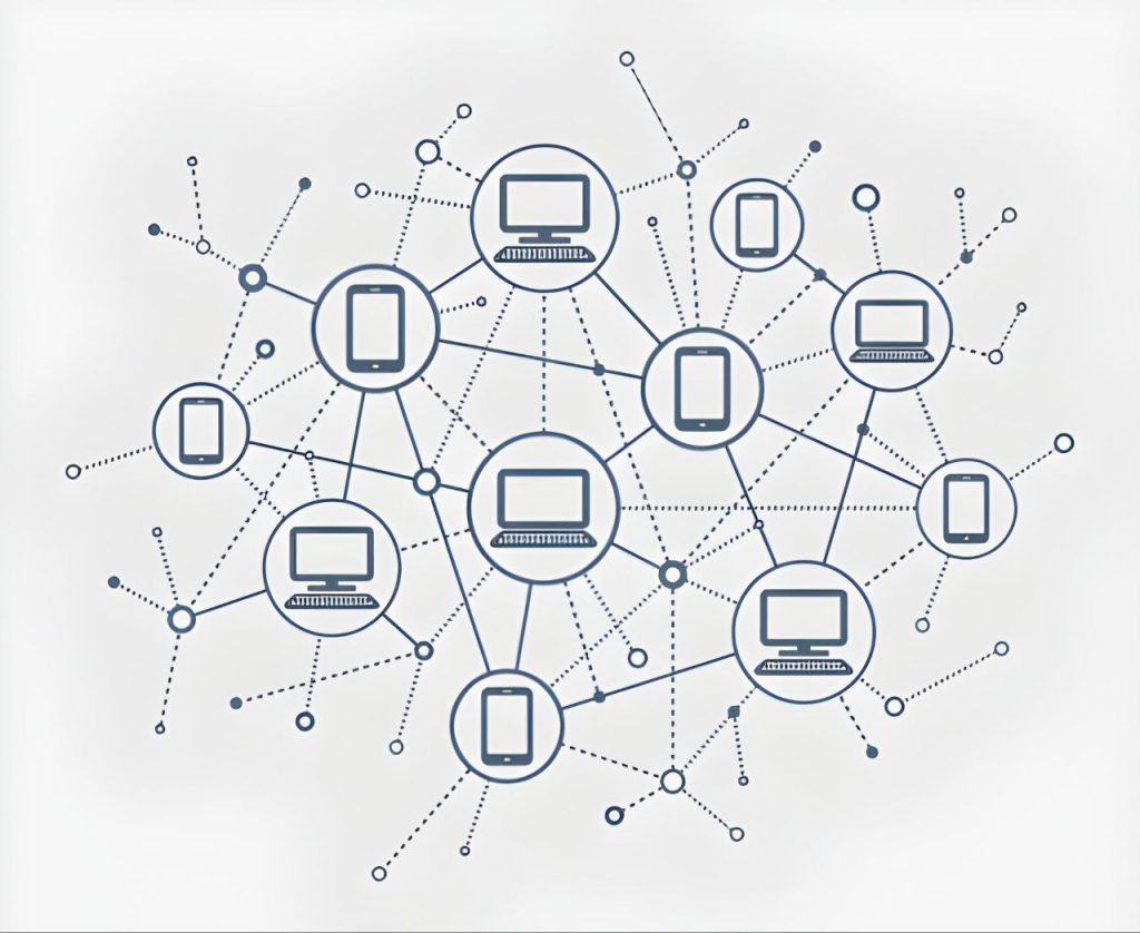
Computer networking is the practice of connecting computers and other devices so they can communicate and share data. In simple terms, a computer network is a group of devices linked together (often called nodes) via communication channels, allowing them to exchange information and share resources. Modern life relies heavily on networks – from browsing the web and sending emails to streaming video and enabling smart home gadgets, networks form the backbone of our digital world.
In this comprehensive guide, we’ll explore the fundamentals of computer networking in an accessible way. We’ll start by defining what networks are and why they’re important. Then we’ll dive into how networks work, the types of networks (like LANs, WANs, etc.), and the key components (such as routers and switches) that make networking possible. We’ll discuss common network topologies (bus, star, ring, mesh, etc.) and explain the famous OSI model and the simpler TCP/IP model, including major protocols like HTTP, FTP, DNS, and more. We’ll look at IP addressing (IPv4 vs IPv6), the roles of DNS and DHCP, and compare client-server vs peer-to-peer networks. We’ll also contrast wired and wireless networking, touch on basic network security (firewalls, encryption, VPNs), and highlight essential network diagnostic tools (ping, traceroute, etc.). Finally, we’ll consider real-world networking examples in home, enterprise, cloud, and IoT contexts.
Whether you’re a beginner or just looking to solidify your understanding, this guide will provide a clear, structured overview of computer networking fundamentals. Let’s get started!
What Is Computer Networking and Why Is It Important?
Computer networking refers to connecting multiple computing devices (computers, servers, printers, smartphones, IoT gadgets, etc.) so they can communicate and share information and resources. In a network, each device (node) can send or receive data to others through some kind of link (wired or wireless). By enabling communication and resource-sharing, networks make many modern applications possible.
Importance of networking: Computer networks have revolutionized how we work, play, and communicate. Here are some key reasons networks are so important:
- Communication and Collaboration: Networks allow people to communicate instantly via email, messaging, video calls, and more. For example, the Internet (a global network) enables billions of users to share information and stay connected in real time.
- Resource Sharing: Networks let devices share resources like files, printers, and Internet connections. In a home or office LAN (Local Area Network), multiple computers can share a single printer or access a common file server, improving efficiency and saving cost.
- Data Access and Remote Work: Networks enable remote access to data and systems. You can retrieve a document from your office server while at home, or control a smart thermostat from your phone over the Internet. This connectivity supports remote work, cloud computing, and IoT.
- Internet and Information Access: Through networking, we have the Internet – a vast Wide Area Network connecting the globe. This provides access to an enormous wealth of information, online services, e-commerce, streaming entertainment, social media, and much more.
- Efficiency and Productivity: By sharing information and resources quickly, networks greatly increase productivity. Businesses rely on enterprise networks for mission-critical operations – if the network goes down, work often grinds to a halt.
- Scalability and Flexibility: Networks can grow as needed (adding more devices or expanding coverage) to accommodate more users or services. A well-designed network scales to support new applications (e.g. adding IoT sensors to an existing network for smart monitoring).
In summary, computer networks are foundational to modern computing. They enable everything from basic communication (like sending an email) to cutting-edge innovations (like cloud services and the Internet of Things). A simple way to think of a network is as the digital “nervous system” connecting various parts of a computer ecosystem. Now, let’s look at how data actually flows through a network.
How Networks Work: The Flow of Data Between Devices
When you send a message or request data over a network (for example, loading a webpage on your laptop), a lot happens behind the scenes. Networking protocols – which are like agreed-upon rules or languages – govern how devices talk to each other and how data is packaged and transmitted. Here’s a simplified overview of how data flows between devices in a network:
- 1. Data is broken into packets: Large messages are divided into smaller chunks called packets. Each packet carries a piece of your data plus header information like addresses and sequencing. This is similar to writing a long letter and putting it into multiple envelopes – each envelope has the destination and return address.
- 2. Addressing and routing: Every device on a network has a unique address (like an IP address) that identifies it. When you send data, your device labels packets with the destination’s address. Networking devices called routers then use these addresses to forward packets along the best path through the network to reach the target. This process is akin to the postal service reading the address on an envelope and routing it through post offices until it reaches the recipient.
- 3. Transmission over media: The packets travel from your device to the network via some transmission medium. This could be a wired medium like Ethernet cables or fiber optics, or wireless signals like Wi-Fi radio waves. The data is converted into signals (electrical, light, or radio) that propagate over the medium.
- 4. Hops through network devices: On the journey, packets may pass through multiple intermediate devices:
- Switches forward packets within a local network, sending data only to the specific device intended (using MAC addresses at the data-link layer).
- Routers connect different networks (like your home network to the Internet) and make routing decisions to guide packets toward their destination IP address.
- Each “hop” between routers/switches moves the packet closer to the target. If any link is congested or down, routers can choose alternate paths (much like detours in a road system).
- 5. Error checking and flow control: Networking protocols include mechanisms for reliability. For example, the TCP protocol on the transport layer ensures that packets arrive intact and in order – if some packets are lost or corrupted, it will retransmit them. This is akin to getting a delivery confirmation or re-sending a lost package.
- 6. Reassembly and delivery: When packets reach the destination device, they are reassembled into the original message. The device’s network software (following protocols) reorders packets if needed and passes the complete data up to the appropriate application. For instance, your web browser receives all the packets of an HTML page and then renders the webpage.
Analogy – the Postal System: A common analogy is that a network works like a postal service. Your data packets are like letters. They get stamped with addresses and make their way through a series of post offices (routers) that decide the best route. The letters might travel by different routes but eventually arrive and are reassembled into the original message. This layering of tasks (writing the letter, addressing envelope, transporting, delivering, etc.) corresponds to different layers in network communication (which we’ll discuss under the OSI model).
The key point is that networks use structured rules (protocols) at each step to ensure data gets from point A to point B correctly. Each device on the network must follow these rules. For example, the Internet uses a suite of protocols called TCP/IP, which we’ll explore later, to handle addressing, routing, and error checking.
Now that we have a basic idea of how data moves in a network, let’s look at the different types of networks you might encounter, from your personal gadgets to the global Internet.
Types of Networks: LAN, WAN, MAN, and More
Networks can be categorized by their size, coverage area, and purpose. Here are some common types of networks:
- PAN (Personal Area Network): A very short-range network centered around an individual. It typically spans just a few meters (1 to 10 meters) and connects personal devices like smartphones, laptops, tablets, or wearables. For example, connecting your phone to wireless earbuds via Bluetooth forms a PAN. PANs are usually low-range, high-speed, and easy to set up (often using technologies like Bluetooth or infrared).
- LAN (Local Area Network): A network covering a limited local area such as a home, office, or campus – typically up to a couple of kilometers at most. LANs connect computers, servers, printers, and other devices within this area for resource sharing and communication. They usually offer high data rates and low latency. Common LAN technologies include Ethernet (wired LAN) and Wi-Fi (wireless LAN). For example, the network in your home or a small office, where all devices are connected to a single router, is a LAN.
- WLAN (Wireless LAN): This is simply a LAN that uses wireless connections (Wi-Fi) instead of cables. A WLAN allows devices to connect over radio waves via an Access Point (wireless router) within a local area. Most home networks and public hotspots (like cafe Wi-Fi) are WLANs. They provide the flexibility of mobility, though wireless can be slightly less stable or slower than wired in some cases.
- CAN (Campus or Corporate Area Network): A network that spans multiple LANs within a limited geographical area like a corporate campus or a university. A CAN links several buildings or LAN segments together. It’s larger than a single LAN but smaller than a city-wide network. For example, a university CAN might connect departmental LANs across a campus, allowing students and staff to share resources. CANs typically use high-speed links (like fiber optics) between buildings and are owned/managed by the organization.
- MAN (Metropolitan Area Network): A network that covers a city or a large town (roughly 5–50 km range). MANs are bigger than LANs/CANs but smaller than nationwide networks. They often connect multiple LANs across a city, for instance linking various branches of a city’s libraries or government offices. MANs may use technologies like Metro Ethernet, fiber rings, or microwave links. Their speeds are typically moderate (higher than WAN, but often lower than a LAN) and they can be costly to maintain due to the area covered.
- WAN (Wide Area Network): A network that spans a large geographic area – from across cities and countries to worldwide. The Internet is the largest example of a WAN, connecting networks across the globe. WANs often consist of multiple LANs or MANs connected through public networks (like telephone lines, fiber optic backbones, or satellite links). They usually have lower data rates compared to LANs and higher latency, due to long-distance transmission and the complexity of routing. Organizations use WANs to connect their branches in different regions. WAN technologies include leased lines, MPLS, or VPN tunnels over the Internet. WANs tend to be high-cost and involve telecom infrastructure; reliability and throughput are key considerations.
- GAN (Global Area Network): A GAN spans unlimited distances around the world, essentially connecting multiple WANs. In practice, the term can refer to networks using satellite communications or the entire collection of interconnected networks forming a global system. The Internet itself can be considered a global network (GAN) since it links WANs and LANs worldwide into one massive network. Large multinational companies might have private global networks using a combination of terrestrial WAN links and satellite links to ensure connectivity across continents.
Each of these network types serves different scope and needs. For instance, home networks are usually LAN/WLAN, business networks might include LANs that connect via WAN to branch offices, and mobile/cellular networks (like 4G/5G) form MANs/WANs covering wide areas. Often, networks are interconnected; for example, your home LAN connects to your ISP’s WAN (the Internet), which is a GAN of sorts.
To summarize the range: PAN (a few meters, personal devices) → LAN (building-level) → CAN (campus-level) → MAN (city-level) → WAN (country or global) → GAN (worldwide integration). All these network types share similar principles but differ in scale, technology, and management.
Now that we know the kinds of networks by scope, let’s examine the components that make up a network and how they function together.
Key Components of a Network
Networking involves various hardware and software components, each playing a role in moving data from one point to another. Here are the key components of a typical network:
- Network Interface Card (NIC): Every device in a network needs a network interface to communicate. A NIC (also called a network adapter) is the hardware in your computer or device that allows it to connect to a network. In modern PCs, the NIC might be an Ethernet port for wired connection or a Wi-Fi adapter for wireless. The NIC handles sending and receiving data as electrical signals (or radio waves) on the network cable or air. It also has a unique identifier (MAC address for Ethernet/Wi-Fi) used for local network communication. In short, the NIC is the bridge between your device’s internal data and the external network.
- Cables and Transmission Media: If the network is wired, cables are used to connect devices. Common cable types include twisted-pair Ethernet cables (CAT5/6) used in LANs, coaxial cables (older networks and cable internet), and fiber optic cables for high-speed or long-distance links. Fiber cables use light signals and offer very high bandwidth over long distances (commonly used in backbone networks and WANs). Wireless networks use radio frequency bands (like 2.4 GHz or 5 GHz for Wi-Fi) instead of cables – so the “medium” is the air. The choice of medium affects speed, range, and reliability: for example, wired Ethernet is often very fast and stable, while Wi-Fi offers convenience of mobility at the cost of some speed and susceptibility to interference.
- Repeater and Hub: These are simple devices used in earlier or small networks:
- A repeater amplifies or regenerates signals to extend the range of a network. For example, on a long cable, a repeater can boost the signal to travel further.
- A hub is a basic network device that connects multiple computers in a star configuration but broadcasts all incoming traffic to every port. Every device sees all packets (which can cause inefficiency and collisions). Hubs operate at the physical layer and have mostly been replaced by more intelligent switches.
- Switch: A network switch is like an advanced hub that operates at the data link layer (using MAC addresses). It connects devices in a LAN and intelligently forwards data only to the intended recipient port rather than all ports. For example, if Computer A needs to send data to Computer B on the same switch, the switch learns their MAC addresses and sends the frames only to B’s port. This reduces unnecessary traffic and improves security and efficiency. Switches are fundamental in modern Ethernet networks; they can be small (4-8 ports for home) or large enterprise switches with dozens of ports. They can also be “managed” (configurable for VLANs, QoS, etc.) or “unmanaged” (plug-and-play).
- Router: A router connects multiple networks and directs data between them. Routers operate at the network layer, using IP addresses to make forwarding decisions. A common example is your home router: it connects your home LAN (192.168.x.x addresses) to the wider Internet via your ISP. The router looks at each packet’s destination IP and routes it either toward the local network or out to the Internet. It’s often called a gateway for your network, as it serves as the entry/exit point. Routers enable all computers on your LAN to share one Internet connection and also often provide basic firewalling by isolating the LAN from external networks. In business and ISP networks, powerful routers direct traffic across complex routes, ensuring packets find an efficient path to their destination.
- Bridge: A bridge connects and filters traffic between two network segments (often two LAN segments). Bridges operate at layer 2 (like switches) and are used to join networks while controlling traffic flow. For example, a bridge could connect a wireless network to a wired network and pass only necessary traffic. Modern note: Today, the functionality of bridges is largely incorporated into switches (a switch is essentially a multi-port bridge).
- Gateway: In networking terms, a gateway is any device that connects dissimilar networks, often performing protocol translations. In practice, “gateway” can mean a router (default gateway to other networks), but it can also be a specialized device or software that translates between different protocols or network types. For example, an email gateway might convert email protocols, or an IoT gateway might translate a Zigbee (sensor network) to IP network. Generally, the gateway is a node that your network uses to access an outside network.
- Modem: A modem (short for modulator-demodulator) is needed when connecting digital networks over analog media like telephone lines or cable systems. It converts digital data from your computer into analog signals for the line and vice versa. Common types:
- DSL modem for telephone DSL lines,
- Cable modem for cable TV coax lines,
- Dial-up modem (older) for traditional phone lines. Modems provide Internet access by linking home networks to the ISP infrastructure.
- Wireless Access Point (AP): An access point allows wireless devices (laptops, smartphones, IoT devices) to connect to a wired network via Wi-Fi or other wireless standards. It’s essentially a radio transceiver and bridging device. Many home routers include a built-in wireless AP. The AP transmits and receives radio signals to communicate with Wi-Fi devices and forwards their data to the main wired network (or vice versa). In larger networks, dedicated AP devices are placed strategically to provide Wi-Fi coverage, all connected back to the wired LAN.
- Firewall: A firewall can be hardware or software that monitors and controls network traffic based on security rules. Firewalls are vital for network security (more on this later). A simple example is the firewall in your router, which might block unsolicited incoming connections from the Internet to protect your LAN. Enterprise firewalls are more complex, filtering traffic between internal networks and the Internet according to configured policies (e.g., allowing web browsing but blocking certain ports).
- Others: There are other components like load balancers (distributing traffic among servers), repeaters/extenders for Wi-Fi (to boost signal range), network cables connectors (Ethernet switches, patch panels), etc., but the above are the primary building blocks.
To illustrate, consider a typical home network: Your ISP’s line comes into a modem (or modem-router combo). The router (often integrated with a wireless AP and switch) then distributes connectivity to your devices. Wired devices plug into the router’s switch ports via Ethernet cables, while wireless devices connect to the router’s AP over Wi-Fi. Each device’s NIC interfaces with this network. The router likely has a built-in firewall for security, and it acts as the gateway to the Internet. This small network contains many of the key components working together.
Understanding these components is crucial, as they all have distinct roles. Next, we will see how devices can be arranged in a network – the concept of network topologies.
Network Topologies (Bus, Star, Ring, Mesh, Hybrid)
Network topology refers to the layout or structure of how devices (nodes) are interconnected in a network, both physically and logically. It’s essentially the network’s shape. Different topologies have different characteristics in terms of performance, reliability, and scalability. Let’s look at the main topology types:
Representation of various network topologies (e.g., bus, star, ring, mesh) showing how network nodes can be arranged.
- Bus Topology: In a bus topology, all devices are connected to a single central cable (the bus). This one backbone runs through the network, and each node taps into it (like stations along a bus route). When a device sends a signal, it travels in both directions along the bus and is received by all devices, but only the intended recipient actually processes it. Advantages: It’s simple and uses minimal cable – just one main run. It was common in early Ethernet (10BASE-2 or 10BASE-5 coaxial cable networks). Disadvantages: Limited cable length and number of nodes; performance degrades with more traffic. A major downside is if the main cable fails, the entire network goes down. Also, two devices transmitting at once can cause collisions (early Ethernet used protocols like CSMA/CD to handle this). Bus topology is mostly of historical interest now, replaced by star (Ethernet switched) topologies.
- Star Topology: In a star topology, all devices connect to a central device (like a switch or hub) with their own dedicated cable. The central node acts as a hub (not to be confused with network hub device) to pass along messages. For example, modern Ethernet networks are a star topology with a switch at the center and each computer plugged into the switch. Advantages: Easy to install and wire (each device has a single connection). It’s also easier to identify faults – if one cable/device fails, it doesn’t typically affect others, just that one connection. Star networks are reliable in that sense (except if the central hub fails). Performance is better than bus because each link only carries the traffic for that two endpoints. Disadvantages: It uses more cable (each node needs its own run to the center). Also, the central device is a single point of failure – if the switch/hub goes down, the whole network is offline. Nonetheless, due to the prevalence of switches (which effectively manage traffic), star is the dominant topology for LANs today.
- Ring Topology: In a ring topology, each device is connected to exactly two neighbors, forming a circular data path (each device has an upstream and downstream neighbor, and data travels around the ring). Each node receives data from its previous neighbor and forwards it to the next, so data moves in one direction (or in dual-ring networks, two directions for redundancy). Advantages: It can be simple and every node gets equal access turn-by-turn (especially if using a token-passing protocol). For example, legacy Token Ring networks used a ring topology where a “token” circulates and a node must possess the token to send data, which prevents collisions. Disadvantages: If any single node or link fails, it can break the loop and bring down the network (unless there are fault tolerance measures). Also, as more devices are added, the latency increases (data might pass through many hops). Ring topologies aren’t common in Ethernet LANs today, but they exist in some MAN/WAN scenarios and older LAN tech. FDDI (a fiber network) also used dual rings for redundancy.
- Mesh Topology: In a mesh topology, every node is connected to every other node directly (in a full mesh), or at least to multiple others in a partial mesh. This creates many redundant paths. Advantages: Highly resilient – if one link or node fails, data can take another path. Mesh networks can handle high traffic since multiple routes exist; they’re often used in critical networks (e.g., telecom backbones, some wireless ad-hoc networks) where reliability is crucial. Disadvantages: A full mesh requires a lot of connections – the wiring or signaling complexity grows quickly with number of nodes (number of links ≈ n(n-1)/2 for n nodes). This is costly and often impractical for large networks. Partial mesh is more common: e.g., each node connects to a few others in a way that there are still multiple routes between any two nodes. An example of a mesh network in practice is the Internet’s underlying topology (routers have multiple connections to different routers), or wireless mesh Wi-Fi systems in homes where each access point connects to several others, not just a single base.
- Tree Topology (Extended Star): A tree topology is essentially a hierarchy of star networks. It looks like a branching tree structure with a root node (often a switch) connected to secondary switches which in turn connect to devices (stars of stars). It’s sometimes called an extended star. Advantages: It allows expansion of the network in an organized way, and isolates segments (each branch could perhaps operate independently). It’s used in many enterprise networks with core, distribution, and access layers of switches (hierarchical design). Disadvantages: It still inherits the dependency on certain central nodes – if an upper-level switch fails, all branches under it are affected. But it’s more scalable than a single star for large networks. This topology is common in structured wiring of large networks.
- Hybrid Topology: A hybrid topology is simply a combination of two or more different topology structures. Real-world networks often aren’t pure single topologies; they mix to suit needs. For example, you might have multiple star LANs in different offices connected in a bus or ring fashion between offices – that’s a hybrid of star and bus. Or a star of stars (tree) is a hybrid. Hybrid topologies aim to leverage strengths and mitigate weaknesses of each constituent topology as needed. One example: a star-bus hybrid, where groups of nodes form stars, and those star hubs are connected by a long bus. Another: star-ring network, used in some MANs, where LAN switches in each building (stars) are connected in a ring for redundancy. The flexibility of hybrid designs often makes them practical for large-scale networks.
In summary, star topology is prevalent in LANs (thanks to Ethernet switches), mesh is seen in high-reliability networks or wireless meshes, bus and ring are mostly legacy or specialized use. Tree/hybrid architectures are used to build scalable networks that can cover larger areas or more nodes by combining topologies.
The choice of topology affects network performance and reliability – for instance, a bus is cheap but a single break is catastrophic, whereas a mesh is robust but expensive. Modern networks tend to emulate the benefits of mesh (redundancy) while using stars/trees for manageability.
With an understanding of how devices can be connected, let’s move on to the rules and standards they follow to communicate – this is where network models like OSI come in.
The OSI Model: Seven Layers of Networking
When multiple computer systems communicate, they do so in an organized, layered fashion. The OSI (Open Systems Interconnection) model is a conceptual framework that standardizes this communication process into 7 layers, each with specific functions. Think of it as breaking down the complex task of network communication into manageable steps, where each layer handles one aspect and passes data to the next layer. The OSI model is widely used as a reference to understand how different networking protocols and devices interact.
The seven layers of the OSI model (from Layer 1 at the bottom to Layer 7 at the top) are:
Illustration of the OSI 7-layer model, which divides network communication tasks into layers from the Physical (Layer 1) up to the Application (Layer 7).
- Physical Layer (Layer 1): This is the lowest layer, concerned with the physical connection and signal transmission. It deals with raw bits and the hardware means of sending and receiving data (electric pulses, light signals, radio waves). Key functions include defining cables, connectors, frequencies, and bit signaling (voltage levels, modulation, timing). Devices at this layer: network adapters, repeaters, hubs, and media (Ethernet cables, fiber optics, Wi-Fi radio). For example, the physical layer specifies that Ethernet twisted-pair cable uses specific pins and electrical voltages to represent 0s and 1s. If two devices are connected, the physical layer ensures that when one puts bits onto the wire, the other receives the same bit stream. It’s all about transmitting bits without regard to meaning.
- Data Link Layer (Layer 2): This layer handles node-to-node data transfer and deals with frames (structured packets of bits) and physical addressing. It ensures that messages are delivered to the correct device on a given network (using MAC addresses) and can provide error detection/correction for frames. The data link layer is often divided into two sublayers: LLC (Logical Link Control) which manages multiplexing and flow control, and MAC (Media Access Control) which manages access to the physical medium and hardware addressing. Devices/protocols: network switches and bridges operate here, as do Ethernet protocol, Wi-Fi’s link layer, etc. For example, when your computer wants to send data to another computer on the LAN, it creates an Ethernet frame with the destination’s MAC address and source MAC, and the data link layer logic in the switch delivers it to the right port. This layer also handles how multiple devices share the medium (e.g., CSMA/CD for Ethernet).
- Network Layer (Layer 3): The network layer is responsible for routing data between different networks and handling logical addressing (like IP addresses). It creates packets that include source and destination IP addresses, and routers use this information to decide how to forward packets through the network. Key protocols: Internet Protocol (IP) is the primary network-layer protocol for the Internet; other examples include IPX (older Novell networks) or ICMP which works at layer 3 for control messages. Devices: Routers are the classic Layer 3 device, since they examine IP addresses and route packets accordingly. At this layer, concepts like subnetting, congestion control, and quality of service can come into play. Essentially, the network layer finds a path through the network for packets – from the source network to the destination network.
- Transport Layer (Layer 4): The transport layer provides end-to-end communication services for applications. It ensures complete data transfer and can offer reliability, ordering, and error recovery. The two most famous transport protocols are TCP (Transmission Control Protocol) and **UDP (User Datagram Protocol)**:
- TCP is connection-oriented and provides reliable delivery: it establishes a connection (handshake), guarantees all packets arrive and in order (through acknowledgments and retransmission of lost packets), and controls flow to prevent overload. It’s used for most applications where data integrity matters (e.g., web HTTP, email SMTP, file transfer FTP).
- UDP is connectionless and “unreliable” (no guaranteed delivery or ordering), but it has lower overhead and latency. It’s used for applications like streaming or gaming where speed is favored and occasional loss is acceptable.
The transport layer works with segments (TCP segments or UDP datagrams). It also includes the concept of port numbers, which help direct data to the right application process on a host (e.g., port 80 for HTTP, port 25 for SMTP). Devices: This is mostly handled in software (the operating system’s network stack). Firewalls can operate at this layer by filtering ports.
- Session Layer (Layer 5): The session layer manages sessions or dialogs between computers. This involves establishing, using, and terminating connections (sessions) between applications. It provides mechanisms for maintaining a dialog, opening and closing communication gracefully, and synchronization points for recovery if needed. In practice, a lot of session management is handled by lower layers (e.g., TCP) or application protocols, so the session layer is less distinct. Examples often cited: RPC (Remote Procedure Call) or SMB (file sharing sessions) utilize session-layer functions. It can also handle things like authentication and reconnection if a session is interrupted. Many modern frameworks don’t explicitly implement session layer protocols; instead these functions are integrated into the transport or application protocols (for instance, HTTP is stateless, but “sessions” are managed at the application level via tokens). Thus, session layer is conceptually important but in the OSI model context, not always separately implemented.
- Presentation Layer (Layer 6): This layer is about data representation – it ensures that the data sent by the application layer of one system is readable by the application layer of another. It deals with things like data format translation, encryption/decryption, and compression. For example, if one computer uses ASCII and another EBCDIC character encoding, the presentation layer would translate between them. Common functions at this layer include:
- Encryption (e.g., SSL/TLS for secure data transmission – often considered between presentation and session layers).
- Compression (reducing data size for efficient transmission).
- Serialization of complex data structures.

In practice, formats like JPEG, PNG, MPEG for media, or data formats like XML/JSON, could be considered presentation-layer aspects since they define how data is structured to be exchanged. However, many of these details are handled by applications or libraries rather than a generic presentation layer. The concept remains: if two applications need to understand each other’s data, the presentation layer is where data is formatted for interchange.
- Application Layer (Layer 7): This is the top layer, which interfaces directly with the end-user applications and processes. It provides network services to user applications. This is where protocols that we interact with operate. Examples include HTTP (web browsing), FTP (file transfer), SMTP/IMAP (email), DNS (domain name service), Telnet/SSH (remote login), and many others. The application layer is what the user or software sees – e.g., your browser uses HTTP at the application layer to request a webpage. The application layer data (e.g., an HTTP GET request) gets passed down through the layers below (presentation, session, etc., down to physical) to send it over the network. On the receiving end, it travels up the layers and finally the target web server’s application layer (HTTP server) processes it. Note: In the OSI context, “application layer” doesn’t mean the actual user interface, but the network protocols and services that applications use to communicate.
One way to visualize OSI is that layers 7–5 (Application, Presentation, Session) deal with the data’s meaning and user interface, layers 4–3 (Transport, Network) handle data delivery between hosts, and layers 2–1 (Data Link, Physical) handle delivery between devices on the same network and the actual signal transmission.
Each layer encapsulates the layer above: e.g., when sending data, an Application layer message gets a Presentation layer encoding, a Session layer header perhaps, then a Transport header (e.g., TCP header with ports), then a Network header (IP addresses), then a Data Link frame (MAC addresses), and finally goes out as bits on Physical. This process is reversed at the receiver (decapsulation).
Why is the OSI model useful? It provides a common language and reference point. It allows different vendors’ equipment and protocols to interoperate as long as they adhere to standard protocols at each layer. For example, an email application doesn’t need to know how Ethernet works (layer 2) or what route the data takes (layer 3); it just needs to send via SMTP (layer 7) and rely on the layers beneath. Network engineers can troubleshoot issues by isolating which layer is causing trouble (e.g., “Is it a physical layer problem – a bad cable? Or a network layer problem – incorrect IP routing?”).
In reality, the OSI model is a reference model. The actual Internet uses the TCP/IP model, which we’ll discuss next, and it condenses some of these layers. But OSI’s seven-layer concept is still taught as a foundational model for understanding networking.
The TCP/IP Model and Major Network Protocols
While OSI is great for conceptual understanding, the TCP/IP model (also known as the Internet Protocol Suite) is the practical model on which the Internet is built. It has four layers that roughly correspond to certain OSI layers:
- Link Layer (Network Interface): corresponds to OSI’s Physical and Data Link layers. It includes all the protocols and hardware for physically delivering data on a network (e.g., Ethernet, Wi-Fi at the local network level).
- Internet Layer: corresponds to OSI’s Network layer. This is where the Internet Protocol (IP) operates, handling addressing and routing across networks. The Internet layer ensures a packet can travel from the source host to the destination host potentially through multiple networks.
- Transport Layer: same concept as OSI’s Transport layer. This includes TCP and UDP protocols (and others like ICMP is often grouped here or Internet layer depending on interpretation) to provide end-to-end delivery services.
- Application Layer: encompasses OSI’s Session, Presentation, and Application layers. In TCP/IP, these distinctions aren’t strictly separated; the Application layer includes all high-level protocols like HTTP, FTP, SMTP, DNS, etc. that operate over TCP or UDP to provide specific networking functions to user applications.
In summary, TCP/IP merges OSI layers 5-7 into one, and layers 1-2 into one. It was developed earlier and independently of OSI, but it became the de facto standard for the Internet. The TCP/IP model is pragmatic – it focuses on the key layers used by Internet protocols.
Major Protocols in the TCP/IP Suite: Let’s go through some of the most important protocols you’ll encounter, organized by layer:
- Internet Layer Protocols:
- IP (Internet Protocol): The fundamental protocol for delivering packets across networks. IP provides logical addressing (IPv4 addresses are 32-bit numbers like 203.0.113.5, IPv6 addresses are 128-bit) and routing. However, IP is unreliable – it does not guarantee delivery or order. It’s a best-effort protocol; higher layers must handle errors. IP’s job is to get a packet from source to destination network. We will talk about IPv4 vs IPv6 addressing in the next section.
- ICMP (Internet Control Message Protocol): Often considered part of the IP layer, ICMP is used for sending error messages and network diagnostics. For example, the “ping” utility uses ICMP Echo Request and Echo Reply messages to test connectivity. Routers might send ICMP “Destination Unreachable” messages if a packet can’t be delivered. ICMP helps with troubleshooting (e.g., traceroute uses ICMP Time Exceeded messages to map hops). It’s not for carrying application data, but for network health feedback.
- ARP (Address Resolution Protocol): ARP translates IPv4 addresses to MAC addresses on a local network (OSI layer 2). When an IP packet is about to be sent on a LAN, the sending host uses ARP to find out the MAC address of the destination IP (if it’s on the same LAN) or of the router (gateway). ARP is like the phonebook of local network addressing. (Note: IPv6 uses a similar concept called Neighbor Discovery Protocol instead of ARP.)
- Transport Layer Protocols:
- TCP (Transmission Control Protocol): As described, TCP provides reliable, connection-oriented service on top of IP. Key features of TCP: 3-way handshake to establish connection; sequence numbers and acknowledgments to ensure ordered delivery; retransmission of lost packets; flow control (slowing down send rate if receiver is overloaded); congestion control (adjusting send rate to network conditions). TCP is used by applications where data integrity is vital (web, email, file transfer, etc.). It assigns port numbers to identify application endpoints on a host (e.g., HTTP server listens on port 80).
- UDP (User Datagram Protocol): UDP provides an unreliable, connectionless service. It just sends packets (called datagrams) without any handshake or guarantee. If a UDP packet is lost, the protocol doesn’t retry – it’s up to the application to handle if needed. UDP has much lower overhead (no need to establish/maintain a connection, no acknowledgment packets). It’s ideal for real-time applications like DNS queries (which are quick and small, and the app can retry if needed) or streaming media, online games, VoIP – where occasional loss is tolerable and timeliness is more important. UDP also uses port numbers (e.g., DNS typically uses UDP port 53).
- (Other transport protocols exist like ICMP technically over IP or newer ones like QUIC over UDP, but TCP and UDP cover the majority of uses.)
- Common Application Layer Protocols:
- HTTP (Hypertext Transfer Protocol): The protocol of the World Wide Web. HTTP defines how web clients (browsers) request resources from web servers and how servers respond. For example, a browser sends an HTTP GET request for a URL, and the server replies with the content (like an HTML page) and a status code. HTTP operates over TCP (usually port 80 for HTTP, port 443 for HTTPS which is HTTP over TLS encryption). It’s a stateless request/response protocol – each request is independent (though cookies and other techniques are used to maintain sessions at the application level). The secure version HTTPS uses TLS/SSL to encrypt HTTP traffic, protecting data in transit.
- FTP (File Transfer Protocol): One of the oldest protocols (port 21). FTP is used to transfer files between a client and server. It establishes a control connection and a separate data connection (which can make it tricky with firewalls). FTP is not encrypted by default, so secure alternatives like SFTP (SSH File Transfer Protocol) or FTPS (FTP over SSL) are often used. FTP illustrates how different commands and responses (like GET, PUT for file actions) enable file operations over a network.
- SMTP (Simple Mail Transfer Protocol): Protocol used for sending emails between mail servers (and from a client to a mail server). SMTP (port 25) is like the postal service for email – it moves messages from the sender’s mail server to the recipient’s mail server. It’s a text-based protocol with commands like HELO, MAIL FROM, RCPT TO, DATA, etc. Email retrieval, by contrast, is done with protocols like POP3 or IMAP by the client, but SMTP handles the transit. SMTP can be secured with TLS (i.e., SMTPS or STARTTLS on port 587).
- DNS (Domain Name System): DNS is often called the “phonebook of the Internet.” It translates human-friendly domain names (like www.example.com) into IP addresses that computers use. When you enter a website, your computer queries a DNS resolver to find the IP of the domain so it can connect to the right server. DNS is a distributed database with many servers worldwide. It uses UDP (port 53) for most queries (for speed), falling back to TCP for large responses (like zone transfers). Without DNS, we’d have to memorize IP addresses, so it’s a critical behind-the-scenes service.
- DHCP (Dynamic Host Configuration Protocol): DHCP automates the configuration of IP addresses and other network settings for devices joining a network. When a new device connects (say your laptop to a Wi-Fi), it can use DHCP to request an IP address lease from the router (DHCP server). The DHCP server assigns an available IP from a pool, along with other details like subnet mask, gateway, DNS servers. This way, users don’t have to manually set up network settings for each device. DHCP uses a series of broadcasts (Discover, Offer, Request, Acknowledgment). It’s built on UDP (ports 67/68).
- SSH (Secure Shell): SSH is a protocol for secure remote login and other secure network services over an insecure network. If you want to control a server remotely via command line, you’d use SSH (instead of Telnet which is unencrypted). SSH encrypts the session (using keys) so that commands and data are safe from eavesdropping. It operates on TCP port 22. Beyond remote shell, SSH can tunnel other traffic and is the basis for SFTP (file transfer) as mentioned.
- Others: There are many other application protocols: Telnet (old, insecure remote login), POP3/IMAP (email retrieval), TLS/SSL (encryption protocol used under the hood for HTTPS and others), SNMP (Simple Network Management Protocol for network device monitoring), BGP (Border Gateway Protocol, crucial routing protocol between Internet providers), etc. Each serves a particular function but all rely on the layers below to get their data across.
The synergy of these protocols enables the Internet and local networks to function. For example, when you browse a website: your computer uses DNS to resolve the domain, then opens a TCP connection to the server’s IP (handshake), then sends an HTTP GET request, gets the response, possibly uses TLS within that if it’s HTTPS. The server’s response travels back in TCP segments, over IP packets, over Ethernet frames on your LAN, etc., and up your stack to the browser which then shows you the webpage. Multiple protocols were at play seamlessly.
One thing to note is the widespread transition from IPv4 to IPv6 due to address exhaustion – let’s address that next.
IP Addressing: IPv4 and IPv6
IP addresses are the unique identifiers for devices on an IP network (much like phone numbers or street addresses for computers). There are two versions in use:
- IPv4 (Internet Protocol version 4): This is the classic IP addressing scheme, using 32-bit addresses (e.g., 192.168.0.1). A 32-bit address allows about 4.3 billion unique addresses (2^32). IPv4 addresses are written in “dotted decimal” – four octets (8-bit segments) separated by dots, like 203.0.113.5. IPv4 served the Internet since its inception, but by the 2010s we essentially ran out of available IPv4 addresses due to the growth of devices. Techniques like NAT (Network Address Translation) mitigate this by letting multiple devices share one public IP, but a longer-term solution was needed.
- IPv6 (Internet Protocol version 6): The successor to IPv4, IPv6 uses 128-bit addresses, written in hexadecimal colon-separated notation (e.g., 2001:0db8:85a3::8a2e:0370:7334). 128 bits allows an astronomically large number of addresses (approximately 3.4×10^38 addresses) – enough for the foreseeable future. IPv6 also simplifies some aspects: it eliminates the need for NAT by providing ample addresses, has built-in security (IPsec is mandatory), and more efficient routing. IPv6 addresses are longer strings (eight groups of four hex digits, but you can omit consecutive zeros). An example IPv6 address: fe80::1c2a:3bff:fe4e:1d%eth0 (with a scope). Transitioning to IPv6 has been gradual – many networks and ISPs support dual-stack (both IPv4 and IPv6).
Differences and concepts:
- Notation: IPv4 in dotted decimal (e.g., 203.0.113.42); IPv6 in hex with colons (e.g., 2001:db8::1).
- Capacity: IPv4 ~4.3 billion addresses; IPv6 practically inexhaustible (for example, IPv6 allows ~10^28 addresses per person on Earth).
- Address structure: IPv4 addresses have classes (historically A, B, C) or use CIDR (Classless Inter-Domain Routing) with subnet masks (e.g., /24 indicating 24-bit network part). IPv6 addresses have a network prefix (often 64 bits for routing prefix, 64 bits for interface ID in LANs).
- Example usage: A home router typically has one public IPv4 address assigned by ISP, and gives out private IPv4 addresses like 192.168.x.x to devices, using NAT to map them. In IPv6, every device can have a unique global IPv6 address, removing the need for NAT.
- Loopback addresses: IPv4 uses 127.0.0.1; IPv6 uses ::1 for loopback (self-referencing address).
- Configuration: IPv4 can use DHCP for config; IPv6 can use stateless address autoconfiguration (SLAAC) where devices generate their own address based on network announcements, often combining network prefix with an interface identifier derived from MAC.
- Coexistence: Currently, most systems run both IPv4 and IPv6 (dual stack). IPv6-only networks are emerging (especially mobile carriers), and mechanisms like tunneling or translation (NAT64) exist to reach IPv4 content.
One important concept in IP addressing is subnetting: dividing an IP range into smaller networks. For instance, in IPv4 a typical home network might be 192.168.1.0/24 which means the first 24 bits are network (192.168.1) and the remaining 8 bits for host addresses (.0 is network identifier, .1 might be router, .255 broadcast, etc.). Subnet masks (like 255.255.255.0 for /24) or prefix lengths indicate how to interpret an IP and route it. In IPv6, similar prefix lengths apply (e.g., an ISP might give a /48 prefix to a site, which can then use /64 subnets out of it).
Overall, IP addressing is fundamental: every device needs an IP to participate in the Internet (even if behind NAT). Understanding IPv4 vs IPv6 and their addressing schemes is becoming increasingly relevant as IPv6 adoption grows.
Now that devices have addresses, how do they find each other by name? That’s where DNS comes in, which we touched on but will detail along with DHCP next.
DNS and DHCP: Naming and Configuring Networks
Two crucial network services that often work in the background are DNS (Domain Name System) and DHCP (Dynamic Host Configuration Protocol). They make network usage much more user-friendly and automated:
- DNS (Domain Name System): As mentioned, DNS translates human-readable domain names into IP addresses (and vice versa). For example, when you type www.google.com, your system needs to find the corresponding IP (say, 142.250.64.78) to connect to Google’s server. It sends a DNS query to a DNS server (resolver) which then either knows the answer or queries other DNS servers in the hierarchy to resolve the name. DNS is often compared to a phonebook or directory for the Internet. Without DNS, we would have to memorize IP addresses for every service – clearly not feasible at scale. DNS is hierarchical: at the top are root servers, then TLD (Top-Level Domain) servers (like .com, .org), then authoritative servers for specific domains. The queries typically go in that order unless cached. DNS records come in various types: A records for IPv4 addresses, AAAA for IPv6, MX for mail server pointers, CNAME for aliasing one name to another, TXT for miscellaneous text data, etc. For users, the important part is: you enter a name, DNS takes care of finding the IP. This happens so routinely (and quickly, often cached locally or by your ISP) that it’s usually invisible until something breaks (like if DNS is down, nothing by name works!). Tools like nslookup or dig let you manually query DNS. In sum, DNS is critical for network operations because nearly all user-level communications start with a name (URLs, email domains, etc.) that must be translated to network addresses.
- DHCP (Dynamic Host Configuration Protocol): DHCP automates network configuration for devices joining a network. Imagine walking into a coffee shop with your laptop or phone. You connect to the Wi-Fi; how does your device get an IP address, the router’s address, DNS server info, etc.? It likely uses DHCP. The DHCP process typically goes:
- Discovery: Your device broadcasts a DHCPDISCOVER message when it needs an IP (it basically shouts “Any DHCP server out there?”).
- Offer: A DHCP server (often the router in home networks) replies with a DHCPOFFER, proposing an IP address and config (subnet mask, gateway, DNS servers, lease time, etc.).
- Request: Your device sends a DHCPREQUEST to accept that offer.
- Acknowledgment: The server sends a DHCPACK to finalize the lease, and now your device configures itself with the provided IP settings.
This happens in seconds when you connect. DHCP also handles renewing leases (after a certain time, the device asks to keep its address or get a new one) and releasing addresses when not in use. Why is DHCP important? It greatly simplifies network management – users don’t have to manually enter network settings on each device; the DHCP server ensures unique IPs and provides correct local parameters. On large networks, DHCP can be centrally managed to allocate IP ranges to different subnets. Without DHCP, configuring devices would be error-prone and tedious.
In combination: When you join a network, DHCP gives your device an IP address, default gateway (router), and DNS server addresses. Then when you try to visit a website, your device asks the configured DNS server to resolve the name, then uses the obtained IP to communicate. So DHCP bootstraps your ability to communicate on the network, and DNS makes that communication user-friendly by handling naming.
From a network operations standpoint, both services are infrastructure elements. DNS ensures that services can be reached via names (which can be updated even if IPs change – a big plus), and DHCP ensures devices can join and leave networks fluidly. Misconfigurations in either can lead to network issues (e.g., if DHCP is down, new devices can’t get on the network; if DNS is down, devices are online but can’t find where to go).
Now that devices have addresses and can resolve names, let’s examine the way they might communicate: client-server vs peer-to-peer.
Client-Server vs Peer-to-Peer Networks
Networks enable different models of communication. Two fundamental architectures are client-server and peer-to-peer (P2P):
- Client-Server Model: In a client-server network, certain computers (servers) are dedicated to providing services or resources, and other computers (clients) consume those services. The server is a central node that hosts resources (files, websites, email, databases, etc.) and waits for requests, while clients initiate requests to the server to use those resources. This model is highly common. Examples:
- A web server (like example.com) serving web pages to many client browsers.
- An email server that clients contact to send/receive mail.
- A database server that client applications query.
Characteristics of client-server:
- Centralization: Servers often centralize control, security, and data (which can be beneficial for management and backup).
- Scalability: Can be scaled vertically (more power to the server) or horizontally (multiple servers behind a load balancer) to handle many clients.
- Dependency: Clients depend on server availability. If the server goes down, clients cannot get service.
- Examples: The vast majority of Internet services: web (HTTP) is client-server (your browser is client, website’s machine is server), DNS itself is client-server (your stub resolver is client, DNS server responds), cloud services are client-server, etc.
Client-server is structured and suits situations with dedicated infrastructure and many clients (e.g., a company file server with many employee PCs as clients).
- Peer-to-Peer (P2P) Model: In a peer-to-peer network, there is no fixed division between clients and servers – each node (peer) can act as both a client and a server to the others, sharing resources more directly. P2P networks are decentralized. Each peer can initiate or respond to requests and usually shares part of its own resources (like storage, processing power, files) with others. Examples:
- File sharing networks like BitTorrent: every participant both downloads and uploads pieces of files to others (after obtaining them). There’s no central server holding the entire file; it’s distributed among peers.
- Some cryptocurrency networks (Bitcoin, etc.) are P2P in that each node communicates with others to propagate transactions and maintain the blockchain.
- Early messaging services or local networks where each computer can share files directly without a central file server (e.g., using Windows file sharing in a small LAN can be peer-to-peer if no central server).
Characteristics of P2P:
- Decentralization: No single point of failure in theory – even if some peers leave, others can still communicate (though network health can degrade if too many leave).
- Resource sharing: Peers contribute resources (bandwidth, storage). In BitTorrent, the more people share, the faster the distribution.
- Scalability: P2P can scale well if each additional peer also contributes resources, distributing the load. However, management of a purely decentralized network can be complex (like searching for data among peers).
- Security/Trust: Without central control, trust and security can be tricky – peers have to abide by protocols and sometimes malicious peers can be an issue if not mitigated.
P2P networks can be structured (using distributed hash tables for indexing content, e.g., Kad network) or unstructured (flood queries to find things). They shine in scenarios like distributed content sharing or collaboration without reliance on a central entity.
Comparison: Client-server is like a library – a central place (server) where clients go to get books. P2P is like a book club where everyone both brings books and borrows from others – no single library, but a network of individuals sharing.
In practice, many systems blend approaches. For example, Skype (in early architecture) was largely P2P for voice data but had central servers for account login. Modern content delivery uses hybrid: CDN servers (as clients of origin server, and servers to end-users) plus sometimes peer assistance.
Use cases:
- Client-server: best for controlled environments, central data (banking systems, corporate networks, typical web services).
- Peer-to-peer: useful for resilience and distribution (torrenting a large file can be faster via P2P when many peers share the load, rather than hammering one server).
Understanding these models helps in designing networks and services. For instance, if you set up a small office network, typically you’ll use client-server for things like file storage (one machine is a file server, others retrieve files). But if those PCs also directly share some folders amongst each other, that’s P2P on a small scale.
Next, let’s consider the medium over which networks operate: wired vs wireless connectivity and their pros/cons.
Wired vs Wireless Networks
Networks can be broadly divided by the physical medium used: wired (using cables) or wireless (using radio waves or other wireless technologies). Each has its benefits and limitations, and often they coexist (e.g., a wired backbone with wireless access for devices). Let’s compare:
Wired Networks: These use physical cables (Ethernet twisted pair, coaxial, fiber optic, etc.) to connect devices.
- Pros:
- Reliability: Generally very stable connections, not prone to interference like wireless. Once it’s plugged in, the connection quality is consistent.
- Speed & Latency: Wired Ethernet can offer high data rates (1 Gbps is common, 10 Gbps and beyond in enterprises) with low latency. Fiber optics can carry enormous bandwidth over long distances (backbone links of 100 Gbps+ are common).
- Security: More difficult to eavesdrop on a wired line without physical access (whereas wireless can be sniffed from a distance if not encrypted).
- No spectrum issues: No need to worry about wireless spectrum congestion or channel overlaps.
- Cons:
- Mobility: Not mobile – device must be physically tethered to the network. Inflexible for laptops, phones, IoT devices that move around.
- Installation: Running cables can be labor-intensive and expensive, especially over large areas or difficult terrains. You need ports and switches to plug into, which can limit where devices are placed.
- Scalability in certain environments: Adding a new device requires a cable run or at least reaching a nearby switch. In a home, there might only be so many Ethernet drops.
Wireless Networks: These use radio frequency (RF) or other wireless methods (infrared, satellite, etc.) to transmit data over the air.
- Pros:
- Mobility: The biggest advantage – devices can move freely and remain connected (e.g., smartphones on Wi-Fi or 4G, laptops using Wi-Fi around the house). Great for environments where wiring is impractical or for transient connections.
- Ease of installation: Setting up a Wi-Fi network can be as simple as powering on a wireless router – no drilling holes or pulling cables. This makes networking accessible in homes and temporary setups (events, etc.).
- Flexibility: It’s easy to add a new wireless device – just connect to the Wi-Fi or pair via Bluetooth, etc., without physical infrastructure changes.
- Cons:
- Speed & Latency: Wireless has historically been slower and higher latency than wired. Modern Wi-Fi (like Wi-Fi 6) can reach impressive speeds (hundreds of Mbps up to gigabit in ideal conditions), but real-world throughput can be lower especially at range or with interference. Wired Gigabit Ethernet still often outperforms Wi-Fi in consistency.
- Interference & Reliability: Wireless is susceptible to interference from other devices (microwaves, other networks, Bluetooth, etc.) and obstacles (walls, metal objects). Signal strength diminishes with distance and barriers, so performance can be inconsistent.
- Security: Wireless signals can be intercepted within their range. Strong encryption (WPA2/WPA3 for Wi-Fi) is essential. A poorly secured Wi-Fi can be abused by unauthorized parties. Wired networks can also be attacked but require physical access to a port or cable tap.
- Capacity and Range: There are limits to how many devices can effectively share the wireless spectrum in a given area. Each access point has finite capacity, and crowded wireless environments (apartment buildings, conferences) can see reduced performance. Range is also limited – Wi-Fi covers maybe a few hundred feet at most, and far less if obstructed (though range extenders or mesh systems can help).
Use Cases:
- Wired: Preferred for stationary devices that need high performance and reliable connectivity: desktop PCs, servers, smart TVs (for 4K streaming stability), gaming consoles (to reduce latency), and infrastructure like switches/routers interconnections. Also used for backbone connections (e.g., connecting different floors via Ethernet or fiber).
- Wireless: Essential for mobile devices: smartphones, tablets, laptops when roaming. Also for IoT gadgets like smart speakers, security cameras (though some use wired power and data). In historical buildings or rented spaces where running new cables is difficult, wireless is a savior.
Often a combination is best: e.g., an office may have wired connections at desks (for performance) but also a Wi-Fi network for convenience with laptops or visitors. Data centers remain almost exclusively wired for obvious performance and reliability reasons, while public networks (like city-wide networks or campus Wi-Fi) are wireless for user access but with wired fiber uplinks.
In summary, wired vs wireless is about trade-offs between performance/stability and mobility/convenience. With each generation, wireless gets better (faster Wi-Fi standards, 5G cellular), closing the gap somewhat, but wired technologies also advance (e.g., 10G, 40G Ethernet for enterprise, fiber to the home). The choice depends on the scenario: you wouldn’t wire an Ethernet cable to your phone while walking, and you wouldn’t use Wi-Fi to connect core routers in an ISP network if you can have fiber.
Now let’s turn our attention to keeping networks secure, a critical aspect as connectivity grows.
Network Security Basics (Firewalls, Encryption, VPNs, etc.)
Networking opens up communication, but with that comes risk – unauthorized access, data interception, malicious attacks. Network security is a broad field, but at a basic level, here are some important concepts and tools:
- Firewalls: A firewall is like a gatekeeper that filters traffic between networks (often between a private network and the Internet). Firewalls can be hardware devices (e.g., in your router or a dedicated appliance) or software on a server/PC. They use a set of rules to allow or block traffic based on criteria like source/destination IP, port, or protocol. For example, a firewall might block all incoming connections from the Internet except those to a public web server. Or it might block outbound traffic to known malicious IPs. Firewalls can also do stateful inspection (allow responses to requests initiated from inside), and deep packet inspection (examining payloads for threats). They are essential to prevent unauthorized access – for instance, the firewall in a home router by default blocks unsolicited incoming traffic, protecting your devices from direct attacks. Enterprise firewalls can be very sophisticated, part of network security appliances that also include Intrusion Detection/Prevention Systems (IDS/IPS).
- Encryption: Encrypting network traffic ensures that even if data is intercepted, it cannot be read without the decryption key. VPNs (Virtual Private Networks) and HTTPS/SSL/TLS are two common encryption applications:
- HTTPS/TLS: When you see https:// in your browser, the communication with that website is encrypted using TLS (Transport Layer Security). This means someone sniffing on the network can’t see the content of your web transactions (like passwords or credit card numbers). TLS uses certificates and encryption algorithms to secure the channel.
- VPN (Virtual Private Network): A VPN creates an encrypted tunnel through the Internet between your device and a VPN server. It’s often used to securely connect remote users to a company network, or by individuals to protect their traffic on public Wi-Fi or to get around geo-restrictions. For example, a remote employee runs a VPN client that encrypts all their office-bound traffic to the VPN server at headquarters; from there, it enters the corporate network. VPN protocols include OpenVPN, IPsec, L2TP, WireGuard, etc.. A VPN essentially extends a private network across a public one securely – it’s like having a “private lane” in the public highway, where only you and authorized parties can see inside the lane.
- Authentication and Access Control: It’s critical to ensure only authorized users/devices access a network or resource. This includes simple measures like strong passwords on Wi-Fi (WPA2 encryption with a passphrase) so only those with the key can join. In enterprise, 802.1X port security can require a device to authenticate (with credentials or certificates) before giving it network access (often used in offices or campus networks for wired ports or enterprise Wi-Fi). Network Access Control (NAC) systems can enforce security policies – e.g., check if a laptop has up-to-date antivirus before allowing it on the LAN.
- Segmentation: Splitting a network into segments (with VLANs, subnets, or different zones) can limit the spread of an incident and control access. For example, putting IoT devices on a separate network segment from sensitive company servers adds security – even if an IoT gadget is compromised, the attacker can’t directly reach critical systems because a router or firewall stands between segments. Network segmentation is a key strategy (think of it as isolating different areas so intruders can’t roam freely).
- Intrusion Detection/Prevention (IDS/IPS): These are systems that monitor network traffic for suspicious patterns that might indicate an attack (intrusion detection) and possibly take action to block them (intrusion prevention). They often use known signatures of attacks or anomalies in traffic patterns. They might be standalone or integrated with firewalls.
- Anti-Malware and Endpoint Security: Though not strictly “network” devices, protecting the devices themselves with anti-virus/anti-malware software, keeping systems updated (patch management) and hardened (closing unnecessary ports/services) complements network security. For example, even with a firewall, if a user downloads malware, endpoint protection might catch it.
- Physical Security: Restricting physical access to networking equipment (lock up the server room, secure network jacks or unused ports) is basic but crucial. An attacker with physical access could plug a rogue device or capture traffic.
- Monitoring and Logging: Regularly monitoring network logs, firewall logs, and using tools to analyze traffic (like a SIEM system – Security Information and Event Management) helps detect security issues early. If an unusual data exfiltration happens at 2 AM or a spike in traffic to a strange IP, good monitoring can alert admins.
- Security Protocols: There are specific network security protocols like IPsec (a suite for securing IP traffic, often used in VPNs to encrypt/authenticate packets at layer 3), SSL/TLS as mentioned for layer 4/5 security, SSH for secure remote management, and SNMPv3 (adds security to network management communications) among others.
Basic best practices include: enabling the firewall on your router and OS, using encrypted protocols (avoid telnet/FTP in favor of SSH/SFTP or HTTPS), changing default passwords on network devices, segmenting what can be segmented (e.g., guest Wi-Fi separate from internal devices), and educating users about social engineering (since a secure network can be undermined if a user lets an attacker in via phishing).
For a home user, network security might mean simply having WPA2 on Wi-Fi, the router’s firewall on, and up-to-date antivirus. For a business, it’s a whole discipline with layered defenses.
Now, given all these pieces, when something goes wrong or we want to examine the network, we use some tools. Let’s cover those next.
Network Tools and Diagnostics
To maintain and troubleshoot networks, IT professionals (and even savvy users) use various tools and commands. Here are some fundamental ones:
- Ping: Perhaps the most iconic network diagnostic tool. The ping command tests reachability of a host by sending ICMP Echo Request packets and waiting for Echo Reply. It reports if replies come and how long it took (round-trip time). Using ping, you can quickly see if:
- Your computer can reach another IP (LAN or internet).
- The latency between you and the target.
- If packet loss is occurring (ping will show if some requests get no reply).
For example, ping google.com will resolve the name to IP and send, typically outputting lines like “Reply from 142.250.64.78: bytes=32 time=15ms TTL=56”. Ping is great for basic connectivity testing. No reply could mean the host is down, unreachable, or blocking ICMP. Some networks disable ping responses for security, so a timeout isn’t always definitive about availability, but often it is the first go-to tool. Think of ping as “Hey, are you there?” and listening for “Yes, I am, and it took X ms”.
- Traceroute (tracert on Windows): This tool maps the route that a packet takes through the network to reach a destination. It does this by sending packets with increasing “TTL” (time-to-live) values and listening to the ICMP “Time Exceeded” messages from routers along the path. The output shows each hop router’s IP (often with its DNS name) and the latency to each hop. For example, a traceroute to example.com might show your router as hop 1, then ISP gateway as hop 2, … up to the destination. This is useful to identify where delays or failures occur. If traceroute stops at some point consistently, it indicates a problem or a firewall beyond that hop. It can also reveal how traffic is routing (which cities or providers it passes through). Each hop usually prints 3 latency measurements (since traceroute sends three packets per TTL increment). Note: Windows tracert uses ICMP, Unix traceroute often default to UDP, but concept is same.
- ipconfig/ifconfig: These commands show the network configuration of your system’s interfaces. On Windows, ipconfig will display your IP address, subnet mask, default gateway, and DNS servers for each adapter. With ipconfig /all, you also see MAC addresses, DHCP info, etc.. On Linux/Mac, ifconfig (or the newer ip addr command) does similar: listing interface names, their IPs, whether they’re up or down. This is essential for verifying what IP your device has, if it’s connected properly, or to release/renew DHCP (ipconfig /release and /renew on Windows).
- netstat: This utility displays active network connections and listening ports on the local machine. Running netstat -an might list all TCP connections (with their states like ESTABLISHED, TIME_WAIT) and UDP endpoints. This can tell you, for example, if your computer has established connections to certain IPs (maybe identifying malware “phoning home” or just checking what connections are open). netstat -b on Windows can even show which executable is associated with each connection (requires admin rights). Netstat is great to see “which ports am I listening on?” (e.g., is my web server process listening on port 80?) or “what connections are currently active?”. It’s a diagnostic for when you suspect a certain service isn’t running or to see network usage.
- nslookup / dig: These are tools to query DNS records. nslookup is simple: you can type nslookup www.example.com to see what IP addresses it resolves to. dig (on Unix) is more powerful, showing detailed info and allowing queries for specific record types (e.g., dig MX example.com for mail exchanger records). If you have DNS issues, these tools help verify if DNS is returning correct results.
- Wireshark: A powerful network protocol analyzer (packet sniffer) that lets you capture and inspect network traffic visually. With Wireshark, you can see every packet your computer sends/receives (on a given interface), decode the protocols, view fields. It’s indispensable for deep troubleshooting – e.g., seeing the full HTTP request/response to debug a web issue, or analyzing handshake of protocols, or diagnosing why a certain device isn’t responding (maybe it never received the correct packet). Wireshark applies filters so you can isolate traffic of interest (like tcp.port == 80 to see HTTP). It is more advanced and typically used by network admins or developers when other simpler tools aren’t enough. One must be cautious and often need admin rights to capture, and on switched networks you usually only capture your own traffic unless using port mirroring or being on the same broadcast domain (or in monitor mode for Wi-Fi).
- Others:
- arp -a: to view the ARP cache (mapping of IP addresses to MAC addresses that your machine knows).
- route print (Windows) / ip route (Linux): to show the routing table, which influences where packets go when leaving your machine.
- speedtest tools: to measure bandwidth to the Internet (often a web or CLI tool contacting a known server).
- telnet / netcat (nc): While telnet is an old protocol, the telnet client or netcat can be used to test raw connections to a port. For example, telnet mail.server.com 25 to see if you can reach a mail server’s SMTP, or use netcat to send custom packets.
- pathping (Windows): Combines ping and traceroute to show path and packet loss at each hop over time.
- Network monitors: On the GUI side, Windows has Resource Monitor or Task Manager (Performance tab) to see network usage per process; similarly, Mac’s Activity Monitor or Linux nload/iftop for interface usage.
These tools help answer questions like: “Is my computer connected? Can it reach the router? The internet? Where does the connection break?” (ping, traceroute), “What’s my IP/DNS/gateway?” (ipconfig), “Is the server listening on the right port?” (netstat), “What DNS info am I getting?” (nslookup), “What exactly is happening on the wire?” (Wireshark).
In troubleshooting, you often go stepwise: ping your gateway – if that fails, local issue; ping an Internet IP (8.8.8.8) – if that fails but gateway works, maybe ISP issue or DNS; ping a domain name – if IP ping works but name doesn’t, it’s DNS. Use traceroute to see where it fails. If a certain application isn’t working, use netstat to see if connections are being made or if the port is listening. Wireshark if needing to dig into protocol details (like seeing a TCP three-way handshake or an HTTP error not visible in browser).
Familiarity with these tools is like having a stethoscope for a network – you can diagnose many common problems.
Finally, let’s look at how all these fundamentals manifest in some real-world network examples.
Real-World Network Examples and Applications
To ground our understanding, let’s examine a few typical network scenarios and how the concepts we discussed come into play:
1. Home Network (Small LAN):
- Setup: A common home network involves a wireless router provided by your ISP or a separate Wi-Fi router. This device often combines a router, switch, firewall, DHCP server, and Wireless Access Point in one. It may also have an integrated modem for DSL/Cable. All your devices – a couple of computers, smartphones, smart TV, maybe IoT devices (thermostat, camera, etc.) – connect either via Ethernet to the router’s LAN ports or via Wi-Fi (WLAN). The router has one interface to the ISP (WAN port) with a public IP, and it assigns private IPs (like 192.168.0.x) to your devices using DHCP.
- Communication: When you browse the web, your device uses DNS (likely the DNS server IP given by DHCP, often the router which forwards to ISP’s DNS) to resolve names. The traffic goes through the router which NATs the private IP to the router’s public IP for Internet. The firewall in the router blocks unsolicited inbound attempts, keeping your LAN safe by default.
- Sharing: Your devices can share files or stream to each other via the local network (e.g., casting from your phone to a smart TV – they discover each other via protocols like mDNS or DLNA on the LAN). The topology is star (all through the router/switch), plus wireless. Speeds might be up to 1000 Mbps between wired devices (if Gigabit) or a few hundred on Wi-Fi, but the Internet speed is often the bottleneck (maybe 50-100 Mbps).
- Security: Home users secure their Wi-Fi with WPA2 passphrase, possibly change the router default admin password, and rely on the router’s firewall. They might use a VPN on a laptop when on public Wi-Fi outside.
- Real example: You have a laptop and phone on Wi-Fi, a desktop wired. The laptop gets IP 192.168.0.101 from DHCP. It pings 192.168.0.1 (router) to check connectivity – success in <1ms. It pings google.com – the router’s DNS (or 8.8.8.8 if you set that) resolves it, then ping goes out – you see ~30ms replies, indicating Internet works. You stream a movie: your smart TV uses DNS to find Netflix servers, connects over the Internet via your router, and the stream flows in. Meanwhile, your phone might print to a Wi-Fi printer – using the LAN.
2. Enterprise Network (Office/Corporate Network):
- Setup: Enterprises have more complex networks. Typically, you have a LAN in an office with many switches connecting PCs, VoIP phones, printers, etc. There’s likely a central core switch connecting to distribution switches on each floor (tree topology). VLANs might segregate traffic: e.g., PCs in one VLAN, IP phones in another, guest Wi-Fi in yet another – all trunked through core switches and separated by a core router or Layer3 switch that also serves as internal firewall between VLANs. There might be a server VLAN hosting things like file servers, database servers. A firewall at the edge connects to the Internet via one or more WAN links (maybe dual ISP for redundancy). The firewall, along with possibly a proxy or IDS, protects the internal network and only allows necessary traffic out/in (e.g., allowing web browsing out, blocking certain ports, and allowing VPN or email in). DHCP servers (maybe on a Windows Server or in network gear) assign IPs to clients in each VLAN; DNS servers (or forwarding to public) resolve names.
- Communication: Internal services (like an intranet site or database) use the client-server model; clients on PCs connect to internal servers via the LAN. The network likely has QoS (Quality of Service) configured to prioritize certain traffic like voice (VoIP) to ensure call quality, and perhaps to throttle less important traffic. For remote branches or remote users, VPNs are used to securely connect back to HQ, effectively extending the corporate network securely over the Internet.
- Internet Access: Often through a unified gateway – e.g., all web traffic may go through a proxy server or firewall that can filter content, scan for viruses.
- Security: Strong emphasis – e.g., network access control might ensure only company laptops can plug in (others go to a quarantine VLAN), Wi-Fi uses enterprise authentication (WPA2-Enterprise/802.1X) tied to individual credentials. Firewalls and IDS monitor traffic for anomalies. Network segmentation limits how far an attacker can move if they breach one machine. Frequent use of VPN for remote workers to tunnel into the network securely.
- Topology: Likely a hybrid of star and mesh. The core network might have redundant links (mesh-like) between core switches and routers for fault tolerance. Multiple branches connect via a WAN (could be MPLS network or site-to-site VPNs) – effectively forming an enterprise WAN.
- Real example: You sit at an office PC. When you log in, it contacts an Active Directory server (client-server). DHCP gave your PC an IP 10.10.5.37 and also AD’s IP as DNS. You access a file share – that goes to a file server on the local network. You join a video conference – your traffic goes out the firewall; the network’s QoS ensures your video packets have priority over someone else’s bulk download. The firewall/NAT uses the company’s public IP to send out to the Internet. Meanwhile, a colleague at home connects via a VPN client – her machine gets a virtual IP in the company range and she can access intranet sites as if she’s local, with encryption shielding her traffic over her home Internet. The network team monitors via a dashboard and sees all is well, no unusual intrusion attempts, and network utilization is at 60%.
3. Cloud Networking:
- Setup: In cloud computing (like AWS, Azure, Google Cloud), networking is virtualized. Companies create virtual networks (like AWS VPC – Virtual Private Cloud) which are logically isolated networks within the cloud provider’s infrastructure. They can define subnets, IP ranges, and virtual routers and firewalls (security groups) in software. Connectivity between servers (virtual machines) in the cloud is handled by the provider’s data center network, which is highly fast and redundant. Cloud networks often tie into on-premises networks via VPN or dedicated links (e.g., AWS Direct Connect) so that the cloud servers appear as an extension of the company’s network.
- Operation: Cloud networks still use the same principles: IP addressing, routing (the cloud provider ensures each VPC’s ranges don’t overlap with others and provides Internet gateways when needed). For example, you might have a web server in a public subnet with a public IP, and a database server in a private subnet (no Internet access). Security is enforced by cloud firewalls (you configure which ports/IPs allowed). Scaling is easier – you can spin up new virtual machines (VMs) and the cloud network assigns IPs and connects them instantly.
- Real example: A small web business hosts its app on AWS. They have a VPC 10.0.0.0/16. Within it, a subnet 10.0.0.0/24 for web servers (with a route to an Internet Gateway so they are accessible) and a subnet 10.0.1.0/24 for databases (no direct Internet). The web server’s security group allows inbound port 443 (HTTPS) from anywhere, and the DB server’s group allows MySQL port only from the web server’s IP. When a user hits the website, DNS resolves to the cloud VM’s public IP, traffic goes through AWS’s network to the VM. When the web server queries the DB, it goes over the private cloud network, isolated from others. The dev ops team can use cloud network monitoring tools to see traffic flows and maybe set up an alert if throughput or latency spikes.
- Cloud and IoT: Many IoT solutions use cloud networks as central hubs. IoT devices (sensors, cameras) might connect to cloud services (over the Internet, possibly via MQTT or HTTP) to upload data. The cloud essentially acts as the server in client-server with IoT devices as clients. For instance, a smart thermostat sends data to a cloud service; your phone app then fetches from cloud – they might not talk directly to each other but through cloud APIs.
4. IoT (Internet of Things) Networks:
- Setup: IoT devices often form their own networks or connect to existing ones. Small-scale IoT (smart home) might use Wi-Fi (smart bulbs on your home Wi-Fi) or specialized protocols like Zigbee/Z-Wave (which then connect via a hub to your LAN). Industrial IoT might use sensor networks with technologies like LoRaWAN, or wired sensors on fieldbus networks that then gateway into IP networks.
- Challenges: IoT networks usually have many devices that send small amounts of data. They often emphasize low power usage (battery-powered sensors). PANs and LANs for IoT (like a personal medical device network via Bluetooth, or a factory floor sensors on a local network) send data to either a local controller or up to cloud.
- Example: A smart city deployment with environmental sensors all around might use a mesh network topology (sensors forwarding data to each other until a gateway). Or they might each have a cellular module to send directly to cloud. On the home side, your smart lock, thermostat, etc., may all connect to a central home hub (over Zigbee, a PAN) which in turn connects to the Internet via your router – combining network types.
- Security and addressing: Many IoT devices get IP addresses via DHCP on local networks; some might not speak IP directly but a gateway translates (e.g., Zigbee devices don’t have IPs, but the Zigbee hub does and it communicates with them and presents an interface to the IP network). A big concern is IoT security – default passwords, lack of encryption – so network segmentation is recommended (e.g., put IoT things on a separate Wi-Fi network or VLAN that has restricted access to your main devices).
These examples show how the principles we covered come together:
- In home and enterprise, client-server and LAN/WAN concepts are clearly seen.
- In cloud, virtualization of network components still obeys IP, routing, firewall rules just abstracted.
- In IoT, diverse network types (some not typical computer networks) still ultimately interface with IP networks to transmit data.
By understanding fundamentals – addressing, routing, protocols, etc. – one can make sense of any network scenario. The specifics change (speeds, media, scale), but at heart, it’s devices communicating according to rules.

Conclusion: Computer networking is a vast field, but at its core, it’s about connecting devices so they can exchange data. We’ve explored what networks are and why they matter, the journey of data from one device to another, different scales of networks (from personal to global), essential hardware (like routers, switches) and layouts (topologies) that form networks, and the layered protocols (OSI/TCP-IP) that ensure it all works reliably. We discussed addressing (how devices find each other with IPs and names), compared architectures (client-server vs P2P), contrasted wired and wireless media, highlighted key security measures to protect networks, and reviewed tools that help us diagnose and maintain networks. Finally, we saw real-world contexts – home, business, cloud, IoT – where these principles apply.
Networking might seem technical, but it underpins nearly every digital activity today. Next time you send an email, join a Zoom call, or ask a voice assistant a question, consider the incredible journey through networks that your data takes: hopping through layers, protocols, and devices, across perhaps thousands of miles, all in fractions of a second – and usually, it just works. Understanding these fundamentals can help anyone appreciate the technology we often take for granted, and for IT professionals, it’s the first step in designing and troubleshooting the networks that keep our world connected.